


Oui, disons que la précision de l'endroit ou tu habites et la grandeur de tes gabarits souhaités. Ainsi que la quantitée. Tes plans sont de quel format. (DXF, SKU, SVG ... etc)
Ma CNC 200 mm x 280 mm. Tu peux aussi subdiviser tes gabarits si c'est plus grands.
mais je suis en Nouvelle-Écosse, Canada....
Bonne chance dans tes recherches. Tu trouveras sans doute quelqu'un dans ton coin.
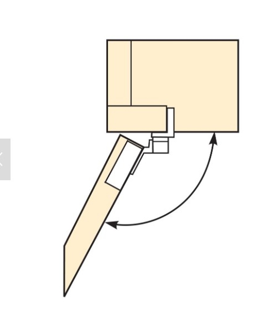
Bonjour, je ne sais pas si tu cherches encore de quoi pour tenir ta pièce.
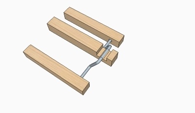
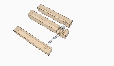
J'utilise du polymorphe. C'est un plastique en granule que tu peux faire fondre à basse température. Il prend la forme de ton objet et après tu n'a qu'a le retirer. C'est réutilisable.
sur un site connu a .... z
cherche Polyshape Polymorph - plastique modelable
je ne retrouve plus le lien. Le gars se servait de ce plastique pour tenir un manche de carabine pour pouvoir incrusté dans le bois des formes différentes. Il serrait son moule de plastique qui contenait le manche dans une étau ordinaire

Bonjour,
quel type de variateur as-tu?
As-tu schéma des bornes variateurs ?
Veux tu que tes boutons existants servent à démarrer le variateur.
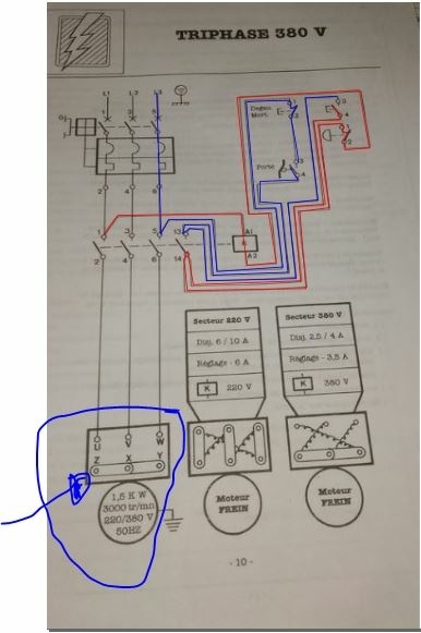
Ce que j'ai remarqué sur tes plans de machines tu as un Bouton champignon pour tout arrêter (Urgence) c'est lui qui a les borniers 1 et 2 sur ton schéma 380 V
borniers 3 et 4 bouton de départ
Tu as aussi un interrupteur fin de course inscris porte
bornier 3 et 4
et tu as aussi un bouton
pour Degau Mort--- 1 et 2 , pas sur de comprendre c'est quoi. Je suis québecois et plus familier avec terme anglais.
En gros voici explication de ton schéma
A l'état arrêt, la bobine (K) reçoit l'alimentation de L1 en A1
A2 va vers la borne 2 de ton bouton Champignon qui est normalement fermé.
puis le courant sort par borne 1 qui va à la borne 14 du relais (K) qui retourne le courant à la borne 4 de ton bouton poussoir et tout s'arrête là tant que tu n'appuie pas sur le bouton de démarrage.
Par la suite
lorsque tu appuie sur ton bouton de démarrage le circuit devient vivant si ta porte est fermée et que DEGAU. MORT n'est pas ouvert.
Alors le relais (K) ferme tout ses contacts entre 1 et 2, 3 et 4, 5 et 6, 13 et 14. Ton moteur démarre alors.
Le circuit est alors auto maintenu tant qu'aucune de ces conditions survient:
Presser bouton champignon
porte ouvre
DEGAU. MORT ouvre
.
Remarque que tu n'as pas besoin de variateur tu as la possibilité de faire les deux choix avec les schémas que tu me présentes.
Vraiment vérifier ton moteur pour les phases
surligné en bleu U,V,W et Z, X, Y.... ATTENTION branchement du moteur
Bon cela me prendrai ton schéma de ton variateur.
et n'oublie pas de vérifier sur ton moteur comment le branché en 3 phases.
Et je répète tu n'as pas besoin de variateur selon schéma Triphase 380
P.S. Je suis technicien senior en contrôle et robotique, je fais cela à longueur de journée. Le bois est ma passion

Bonjour,
voici un calcul de base pour essayer.
En gros voici
TEST FEED = D X 0.02 X F X RPM
Diamètre de l'outil X 0.02 pour Chip Load (Voir spec de l'outil pour le Chip Load)
X Nombre de flutes de l'outil donne total chip load
Donc
Vitesse du moteur X total chip load = inch/min.
Attention <<< c<est Inch/minute)>>>
Et tu plonges le diamètre de l'outil... (Ma machine refuse, c'est trop dure pour moi ce 'Set-up'
Suite à beaucoup d'essai, c'est le seul moyen de savoir vraiment...
Le bois étant une matière naturel les vitesses d'avance change avec le ''Janka''
et si tu vas trop vite, tu vas l'entendre.
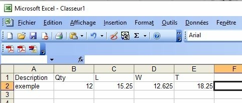
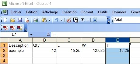
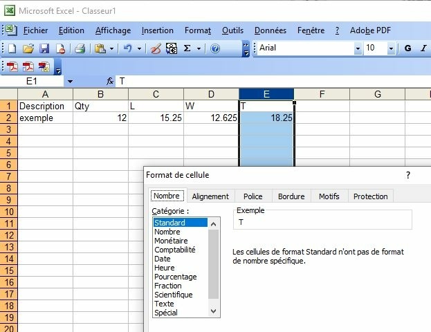
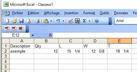
Je peux t'envoyer un fichier Exccel ou LibreOfficeCalc.
Règle du pouce pour ma machine
dia de l'outil divisé par quatre = donne la profondeur pour chaque passe
vitesse 'feed rate' environ 60 Inch par minute
ensuite j'ajuste le 'feed rate' selon ce que j'entend.
L'oreille est ton meilleur guide.
Plunge Rate est la moitié du feed rate.
J'ai une petite CNC.
Bon un copié coller qui parvient de l'endroit ou j'achète mes outils de coupe. C'est sur c'est au Etats-Unis. Leurs outils sont de Superbe Qualité et le prix va avec aussi, mais pour ce que je fais, c'est le top.
Your shopping cart is empty!
Think & Tinker, Ltd.
0 item(s) - $0.00
Search
Selecting the Appropriate Spindle Speed (RPM)
Intro
Cutting Metal
Cutting Wood
Selecting the correct speed (RPM) to use when cutting any material with a rotary tool has always been something of a challenge. Even with the advent of large material reference databases and amazing tools like the GWizard Calulator by
CNCCookbook.com, trying to settle on the "best" RPM for any particular combination of material and cutter can be daunting at the best of times. This is particularly true of materials like wood and plastic where there is such a variation in
cutting properties from batch to batch that no convenient parameter like "SFM (surface feet per minute" can be reliably determined. Nonetheless, there are a few techniques that you can use to arrive at a useable spindle speed, no matter
what you are cutting.
Back in the day, when we all still had our own teeth, the spindles used on CNC routers could be assumed to have been built to relatively stringent specications using hihg-quality components. When compact, low-cost systems started to
proliferate, this situation changed dramatically. To keep costs down, most manufacturers of these "desk-top" units adopted consumer-grade hand-routers as their "spindles" of choice. Made using much looser tolerances and cheaper
materials, hand-routers introduced and number of problems that have to be addressed before locking in the RPM.
You call that concentric? - One of the rst things that became apparent when owners of low-cost CNC tables started using micro-tools was that the nuts and collets that were being supplied by the router manufacturers were simply not
precise enpugh for the task at hand. With high runout (TIR) often accompnaied by low clamping force, many of the collets were found to be downright dangerous to use. Coupled with the frequent need to use equally imprecise collet reducers
to accommodate smaller shank tools, you ended up with a situation that was great for carbide tool manufactureres, but not so good for the end user. Most systems could not successfully use tools with cutting diameters less than 1/32"
(0.8mm), virtually eliminating their use for precision machining, jewelry making and printed circuit (PCB) fabrication. This problem was largely resolved in 2008 with our introduction of PreciseBits Precision Nut & Collet Systems and the arrival
of relativley low-cost VFD spindles in 2010.
Smooth as silk - Any rotating system has speeds where transverse vibration is at a minimum (nodal points) and speeds where the vibration is more pronounced, sometimes violently so (referred to as resonance points, like unbalanced
automobile tires at high speeds). In some cases the dierence between these points is audible but, with well designed spindle/collet/nut/cutter systems, the dierence is more often tactile (you have to feel it to detect it). To improve surface
nish, minimize bearing wear, reduce the cutting noise level and preserve the life of your cutting tools, it is a VERY good idea to ALWAYS operate at a quiet nodal point. If you have a habit of buying high-quality tools (like ours), nding nodal
points is usually quite straight-forward. On the other hand, if you prefer using low cost bits (e.g. 24 router bits for $18.95), it may well prove to be impossible. This is what you should do.
- Load the tool that you will be testing into your collet and make sure that the nut is properly tightened.
Menu
HOME PRODUCTS APPLICATIONS RESOURCES SUPPORT DISTRIBUTORS ACCOUNT - Raise the Z-truck (platform your router/spindle is mounted to) to make sure that the cutting tool is spinning freely in the air.
- Grab the top of your router/spindle with one hand.
- With the bit "cutting" air (zero load), start the motor at the highest SPEED (RPM)
- Assuming that your spindle/router has variable SPEED, reduce the SPEED until you nd the rst "quiet" (nodal) spot (Remember! You are "listening" with your hand, not your ears.).
- Record this SPEED in your process log.
- Continue reducing the RPM until you have identied (and recorded) all of the nodal points for this collet/cutter combination, over the entire SPEED range of your router/spindle.
Do not be concerned if you cannot detect any variation in the "feel" of the spindle / router as you vary the RPM. It just means that any resonance points are so suppresed that they will not have any aect on life of your tools or the quality of
their operation. It is a good idea to repeat this test periodically because the sudden appearance of excess vibration at any RPM can signal that your bearings are starting to wear out and may ultimately need replacing.
Generally speaking, if you are cutting wood (soft or hard) with a tool that is 0.125" dia. or smaller, you can run your spindle as fast as it will go (assuning that it is smooth at that speed).
Thanks to the eorts of researchers at the ASTM and various other standards agencies, coming up with a good RPM to cut most metals is quite easy. With the exception of some exotic alloys, all you have to do is: - Go online and nd the Surface Feet per Minute (SFM) specicaiton for the particular metal you are machining
(e.g. the SFM table for Niagara Tool. Please note that this may vary depending on what kind of tool you are using.) - Multiply the SFM by 3.82 and divide the result by the diameter of the tool (IN INCHES!)
(the magic number, 3.82, converts the feet in SFM into inches at the same time that it converts the diameter of the bit into the circumference) - The nal result is the RPM suitable for cutting the metal with your specic bit.
In other words:
RPM = (SFM X 3.82) / (Cutter Diameter)
Or, you could save a lot of time and eort by purchasing a copy of the G Wizard Calcuator, an essential tool for anyone contemplating serious CNC work.
Silence is golden - When you are cutting a new material, it is often dicult to tell what RPM to use. This is especially true of materials like wood that change from batch to batch and thermolastics where there can be signicant dierences
between cast and extruded products. . Luckily, in many cases, the cutting tool will tell you when it is unhappy. Just like a hungry puppy, it will whine and squeal if you are trying to turn it too fast for the material being cut.
Note: Generally speaking, you will not hear ANY squeal from a bit 1/8 in. or smaller in diameter. So, you can pretty much disregard this step if you are using microtools, which are perfectly happy to work at almost any RPM your spindle is
capable of turning.
A straight forward method for nding the best maximum SPEED is: - Load the tool that you will be testing into your collet and make sure that the nut is properly tightened.
- Set the SPEED to the highest nodal RPM determined above.
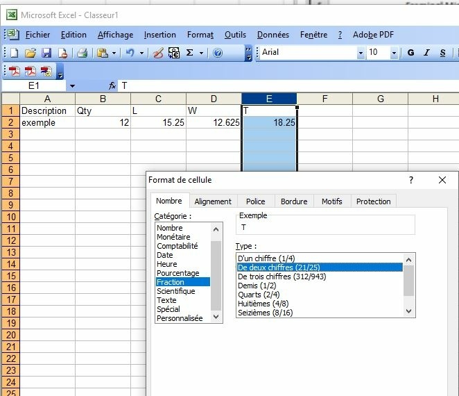
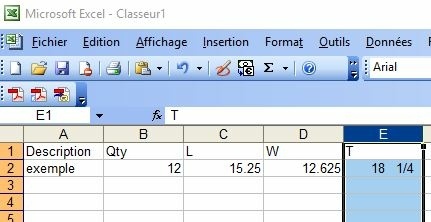
- Calculate the test FEED by:
multiplying the diameter of the bit (D) by 0.02 to determine the CHIP LOAD (2% chip load)
multiply the CHIP LOAD by the number of utes (F) on the cutter you are testing to determine the TOTAL CHIP LOAD
multiply the TOTAL CHIP LOAD by the SPEED (RPM) to calculate the TEST FEED
In other words:
TEST FEED = D X 0.02 X F X RPM
[For example, a good TEST FEED for a 1/4" dia. 2-ute cutter with a SPEED of 12,500 RPM would be:
0.250 in. X 0.02 X 2 (utes) X 12,500 RPM = 125 Inches Per Minute (IPM)] - Program a 3" or 4" long cut, 1 bit diameter deep using the FEED and SPEED just determined.
- Run the program.
- If the bit squeals like a stuck pig, reduce the SPEED and FEED to the second highest nodal point and repeat steps 3 through 6.
- Continue reducing the SPEED and FEED until the sound from the bit has been minimized. The cutting sound may still be quite loud, but should not be a high-pitched wail. If you cannot nd a SPEED where the bit does not squeal, your
router/spindle may not have a low enough SPEED range to cut this material with this tool. Switching to a smaller diameter tool may allow you to nd a combination that works. - Assuming that you nd a suitable SPEED, record it in your process log with any other information associated with this tool.
The is the SPEED that you will use in the Sweet spot test used to nd the optimum FEED rate.
Support
Désolé, c'est en anglais